To be able to estimate the intended trajectory of a person (one of the main deliverables of this project), I need to first be able to estimate the current state (position and velocity) of the arm. And having the images that the depth camera is providing is just not enough. This is because the depth camera can calculate the positions of the joints in 3D space, but the dynamic model of the arm needs to know the joint angles. Therefore, the information from the camera needs to be converted to the format that the model needs it. How can we convert coordinates into angles? The robotics course that I am teaching helped me a lot in this.

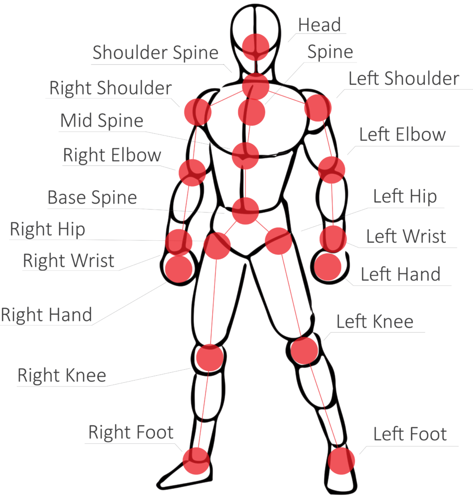
Markers detected by the Astra Pro camera
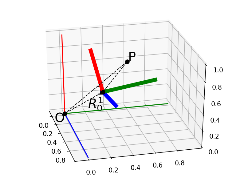
The idea is simple: we construct a ‘fixed’ coordinate frame (e.g. on the torso) and ‘moving’ coordinate frames on each rigid segment of the arm. The idea is to find out how much each rigid segment has rotated relative to the ‘previous’ segment. We call this, a transformation, and if we have coordinate frames attached rigidly on each segment, calculating these transformations is not very difficult. The real problem is: how do we construct the coordinate frames in a fashion that is repeatable and anatomically relevant? The answer is: we create the coordinate frames based on the joint positions.

Transformation from one coordinate frame to another
So here is my idea: For the ‘fixed’ coordinate frame, we use the two shoulder markers and define a vector going from the right shoulder towards the left. The direction of this vector will be the X axis of the fixed frame. The Z axis, is defined by the direction of the vector connecting the middle spine and neck markers. The third axis (Y) can be calculated using the cross product of the Z and X axes. (okay, we also need to re-calculate the X, based on the new X and Y to make sure that the three axes are perpendicular with each other).

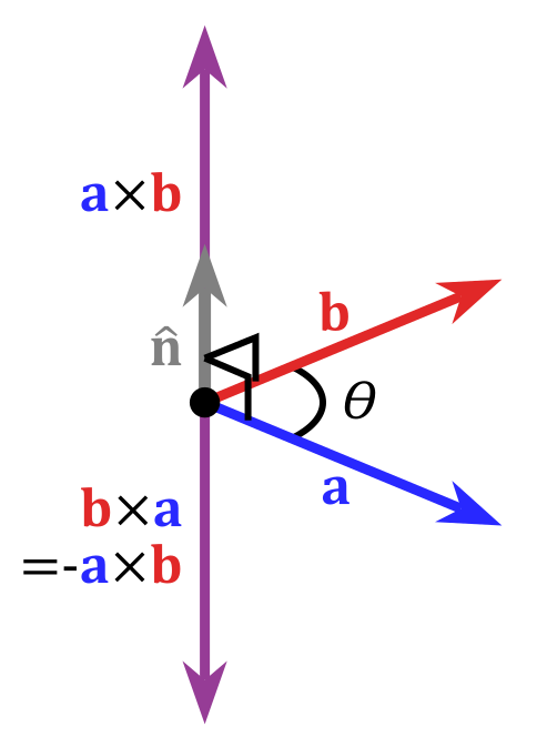
Definition of cross product of two vectors. The result is perpendicular to the original vectores
Then we construct the X axes attached on the humerus and ulna bones. These are simply defined by the markers of the elbow and shoulder (for the X of the humerus) and of the hand and elbow (for the X of the ulna). What about the other axes though? We don’t have any more markers that we could use to determine repeatidely an axis that is perpendicular to the X and is anatomically relevant. That is true, however we can play a bit smart. We know that the axis of rotation of the elbow (the axis around which the ulna is rotating about) is perpendicular to the ulna itself (that’s because it is a hinge joint). It also happens that it is also perpendicular to the humerus bone (by the same definition). Since we have two vectors that we need to find their common perpendicular, we can use the cross product of the two vectors to calculate the Z axis. This is both repeatable, and anatomically relevant, so it solves the problem. We can apply a similar approach for the other joints too.
I have just implemented this for one joint (the elbow), and using the super useful Dynamic Arm Simulator and the skeleton tracker of ROS, I can update the state of the arm model real-time, using data from the camera.
Next step is to implement it for the shoulder. The problem with the shoulder is that it is not a hinge joint, but a ball and socker one. This means that I need to calculate three rotations. This is not as trivial as with hinge joints, since there are different combinations of rotations that can result in the same transformation. But it is not impossible to figure out a repeatable and anatomically relevant way to do.
Update
It’s been a while now that I managed to calculate the shoulder kinematics as well, but I never got to make a nice video like the one for the elbow. I finally did it today, and you can enjoy the full kinematics of the upper arm in the following video:
