During these days, I am visiting the Robotics laboratory of the Nara Institute of Science and Technology, so that I can learn from their experience in Robotics applications and complete a small part of my project (trajectory planning and execution). I have the luck of working with a KUKA iiwa lbr, which is a very serious piece of equipment with some considerable capabilities. It also has increased safety features, very good range of motion and 14kg payload, which makes it a good candidate for a rehabilitation robot.
For making the robot work with my current stack, and more specifically with with the astrapro Orbbec camera, I had to find a way to find out the correct transformation between the coordinate frame of the camera and of the robot. This is needed since all my calculations are happening on the frame of the camera (i.e. skeleton data), however the motion that the robot will perform must be described in the frame of the robot.
The camera though can be positioned in many different ways in relation to the robot. How do we find this transformation?
Calibration patterns
The most common way people are using to solve this problem, is using specific calibration patterns. A specific pattern (usually circles or squares) are printed on a piece of paper and a picture is made from a depth camera. If the shapes on the pattern have known dimensions and arrangement, from the image and depth data, we can calculate the transformation between the camera frame and a frame constructed on the pattern. OpenCV seems to be really good for this kind of stuff.
So, if we put the pattern in a specific position with respect to the robot, then we know the transformation from the pattern to the robot. And if we can calculate with images the transformation from the camera to the pattern, then it is very easy to calculate the transformation from the camera to the robot.
Putting theory in practice
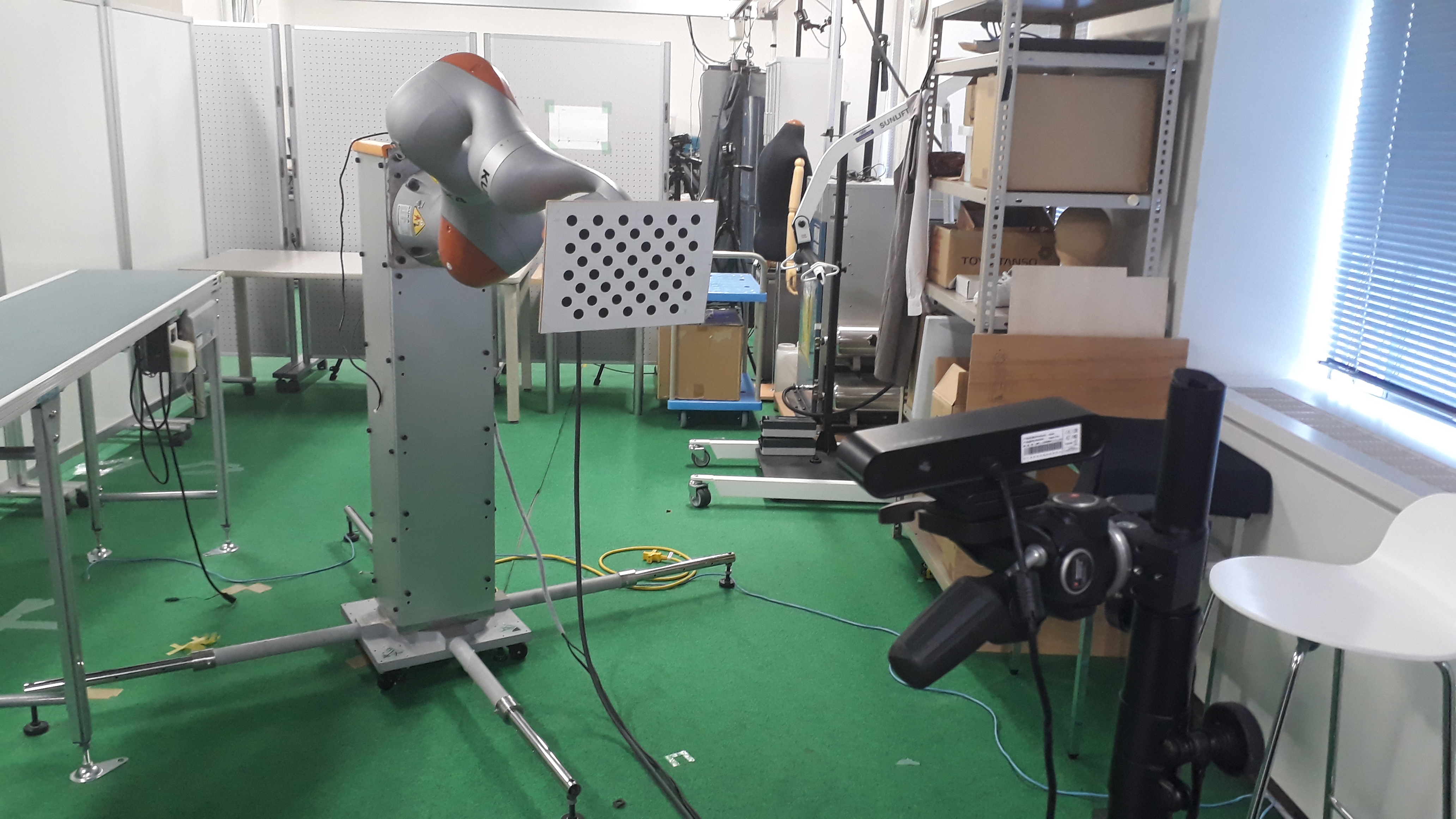
I tried to put this idea in practice, mainly using a ROS package called camera_pose_calibration. The documentation was a bit messy, but I eventually managed to fix some bugs and make it work. I printed an annotated version of the assymetric circle pattern and mounted it on a plate specifically made to be mounted at the end-effector of the robot. The camera was placed on a tripod facing the robot and the pattern.

The calibration pattern mounted, the camera facing it
The method requires just one snapshot to calculate the necessary transformation, but making multiple snapshots is always better.
Results
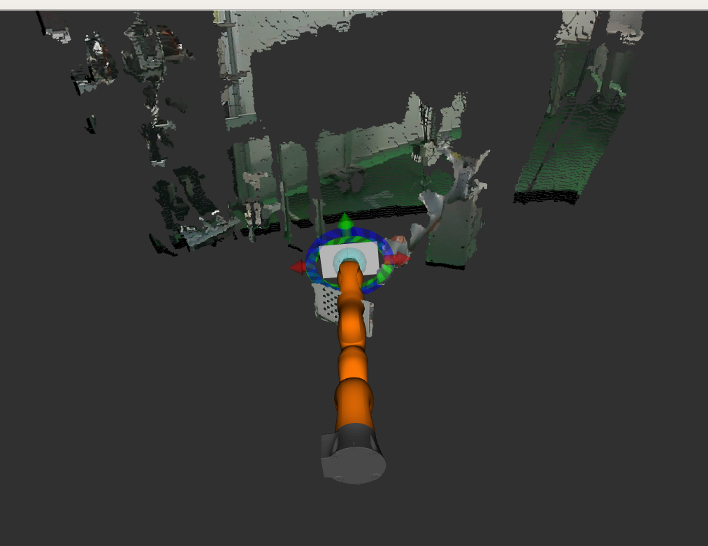
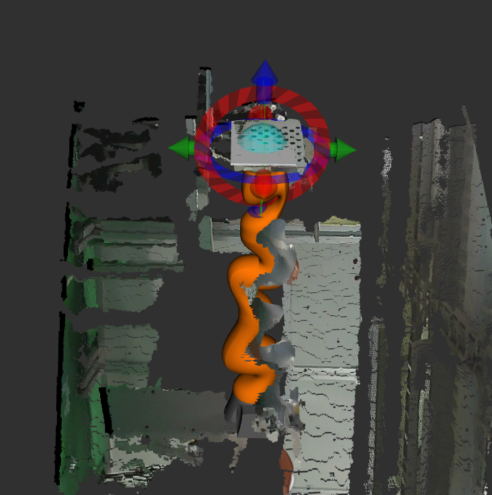
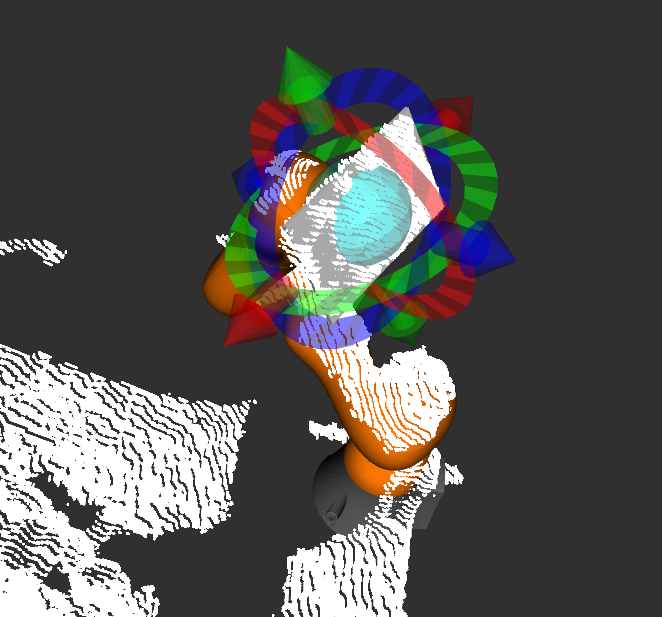
To verify that the calibration is working fine, we can visualise the robot as the camera ‘thinks’ it is positioned on its own frame, together with the image data captured from the camera. We should expect that the robot visualization will coincide with the image data if the calibration works correctly. Bellow you can see the image data and the robot before and after the calibration is performed.

Before the calibration, there is no relation between robot visualization and image data

After the calibration, robot visualization and image data coincide

After the calibration, robot visualization and image data coincide
To make the result event more clear, I tested the robot in different poses. Once the transformation between the camera and the robot is found, then the robot can move and we expect that the robot visualization and the image data should continue to coincide. You can see this happening in the video bellow.
I also tested the calibration with the rest of my code, specifically the one that calculates and visualises the skeleton data. As you can observe in this video, the calibration tag was removed from the robot, since it is not needed anymore after the calibration is performed. In this video, you can also see what actually happens in reality, and you can notice that when I am touching the robot in reality, it is also what happens in the visualization.
Acknowledgments
I would really like to thank the team at the robotics lab here for all their help so far! Especially prof. Ding Ming for all the access to equipment and infrastructure, and for Pedro Uriguen for his help with setting up the KUKA, 2D/3D printing parts and for showing me around the lab.
